4-Channel SPDT Relay Board: RLY104 (Legacy)
- Conveniently add relay outputs to your project
- Provides quick and easy relay wiring
- Four SPDT relays and drivers
- Accepts TTL logic level control inputs
- Available in 5V, 12V, and 24V coil voltages
- Screw terminal connections
- Convenient for CNC projects
- LED indicator for each relay
- Relay contacts rated for 15A at 250VAC
- Available in rubber feet or DIN rail mount
NOTE: These relay boards are no longer being produced by Winford Engineering.
To see the new design with updated hardware, check out the Relay 204 series.
General Description
This relay board provides a convenient way to add relay outputs to your project, allowing you to switch high-current loads such as AC appliances, motors, and more. This board includes four SPDT relays, relay driver circuits, and protection diodes. Simply provide the board with power, connect your logic-level signals to the inputs, and the relay contacts are ready to use. The relay contacts are electrically isolated from the rest of the board, which allows the board to be used in a wide variety of applications, including both AC and DC loads.
With this relay board, any logic-level signal (5V) or higher-voltage signal (up to 30V) can be used to control a relay. Examples of logic-level signals include the outputs of a PC's parallel port, microcontroller output pins, and many others.
The board is available with three different relay coil voltages (5, 12, 24 VDC), allowing you to choose whichever is most conveniently available for your project. Suitable wall power supplies for the 5V and 12V models are available below.
Please note that the relay coil voltage you select has no effect whatsoever on the voltages you can switch with the relay contacts. Also note that the relay coil voltage you select does NOT affect what voltage is needed for the input control signals. For any of the coil voltage options (5, 12, or 24V), an input control signal from 2.7VDC up through 30VDC will activate the relay. See datasheet for input current requirements.
For a similar board without built-on driver circuitry, please click here.
Mounting Options
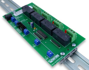
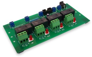
These products are available in two different mounting variants. Product numbers ending with -DIN come with DIN clips already installed and ready to snap onto 35mm or 32mm DIN rail. Product numbers ending with -FT have stick-on rubber feet installed on the bottom side, allowing for benchtop use or panel mounting. For panel mounting, we suggest 1/4" nylon standoffs under the mounting holes, and #6 screws.
RLY104-12V-DIN
 Click image to enlarge.
 Rail not included

RLY104-24V-FT
 Click image to enlarge.
Product Documents
Product Details
- Four SPDT relays and drivers
- Accepts TTL logic level control inputs
- Available in 5V, 12V, and 24V coil voltages
- LED indicator for each relay
- Relay contacts rated for 15A at 250VAC
- Screw terminals for control inputs(accepts 16-26 AWG wire)
- Screw terminals for contacts (accepts 12-24 AWG wire)
- 0.1" header provided for input control signals (in additional to screw terminals)
- Power supply may be connected via DC power jack or via screw terminals.
- Approximate dimensions: 3.0" x 6.2"
- Available in rubber feet or DIN rail mount
NOTE: These relay boards are no longer being produced by Winford Engineering.
To see the new design with updated hardware, check out the Relay 204 series.


